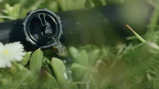
Button Drip Emitters
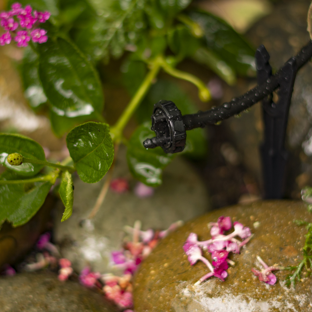
DIG Button Drip Emitters utilize a labyrinth-flow-path design producing a turbulent flow that ensures years of consistent watering with less chance of clogging. Available in flow rates of .5, 1 or 2 GPH and an operating pressure range of 15 to 25 PSI (the higher pressure the higher the flow rate), the button drip emitters can be found in packs of 5, 25, 50 and 100, each with a 1/4″ barbed inlet and small nipple outlet. Recommended for residential and commercial applications, these drip emitters are a low-cost solution for an individual plant, planter boxes, small to large pots, groundcovers, shrubs and trees on short runs, level terrain or low-pressure gravity feed drip irrigation installations, and areas where conventional sprinkler systems are not practical. The button drip emitter is made of two-piece construction and can be taken apart for cleaning, by twisting the top part of the drip emitter counter clockwise and pulling it apart.
Features
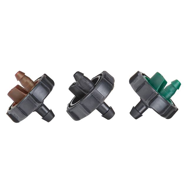
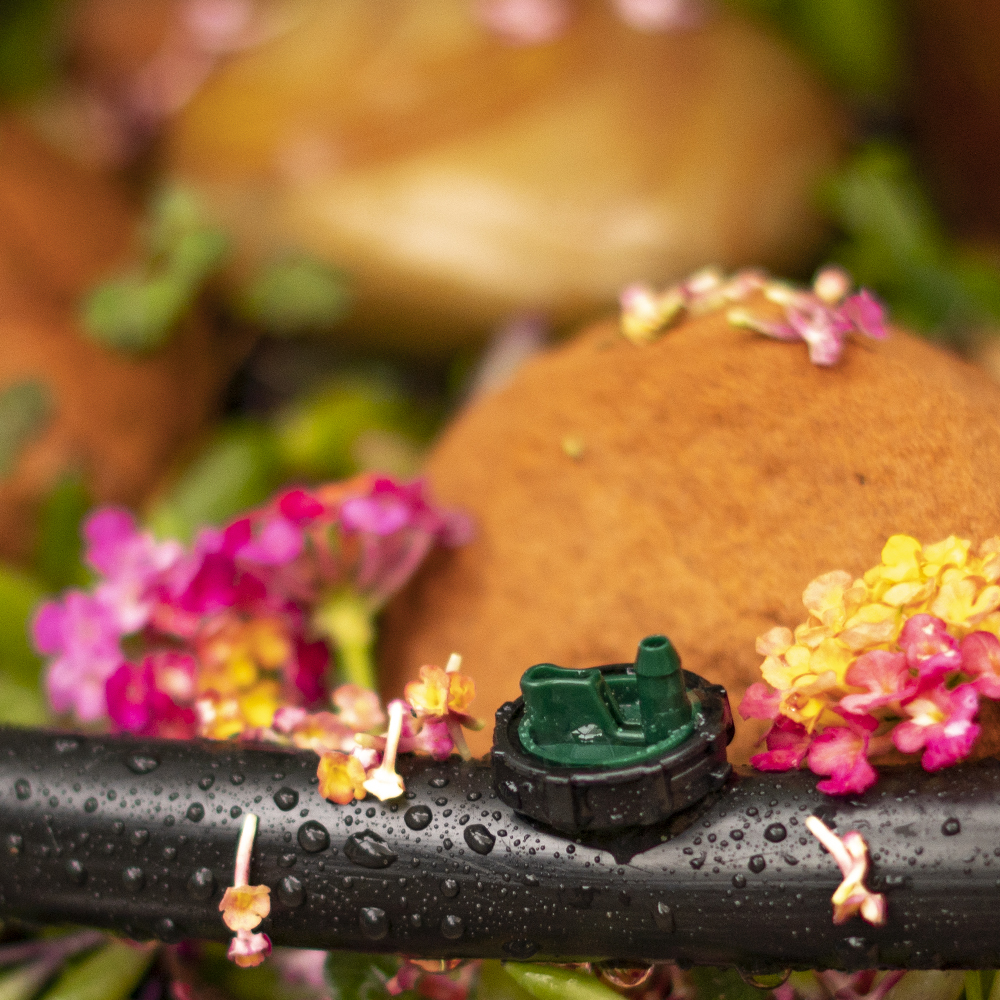
- Color-coded to easily identify flow rate
- Turbulent flow through a unique labyrinth-water-passage design reduces likelihood of clogging
- Uniform flow rate
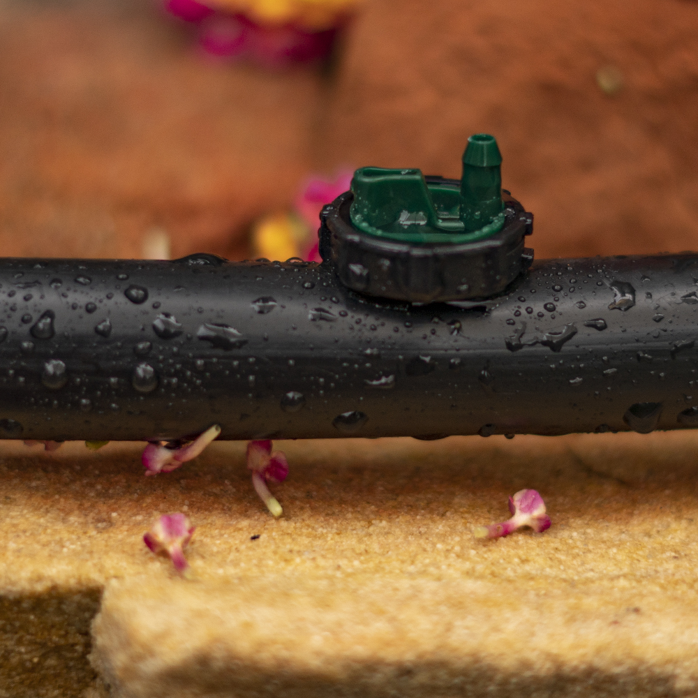
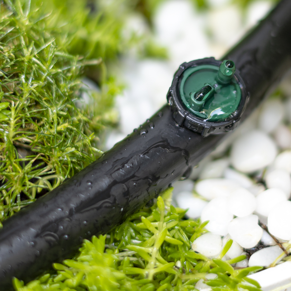
- Raised barbed outlet prevents water runoff along the drip lateral
- Resistant to chemicals and fertilizers used in landscape applications
- Constructed of UV-resistant, durable plastic material to withstand the most adverse conditions
How to Order
| MODEL | DESCRIPTION |
|---|---|
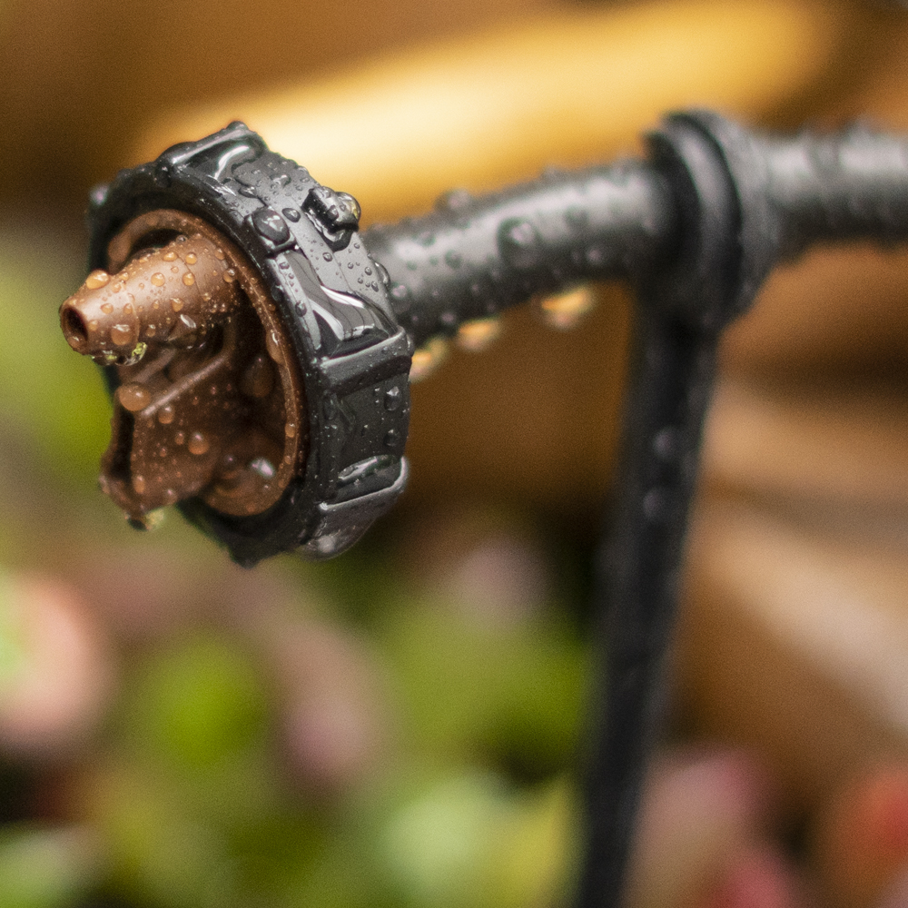
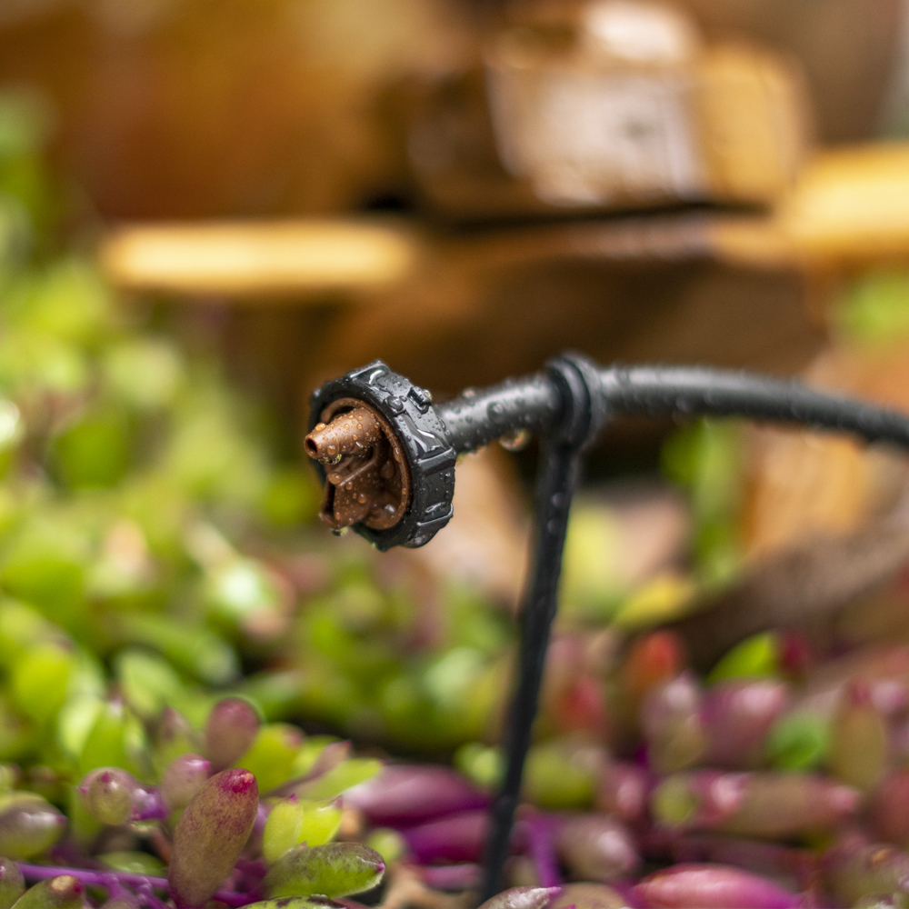
| 0.5 GPH Brown | |
| W2205A | .5 GPH Button Drip Emitter (pack of 5) |
| W2205B | .5 GPH Button Drip Emitter (pack of 25) |
| W2205050 | .5 GPH Button Drip Emitter (pack of 50) |
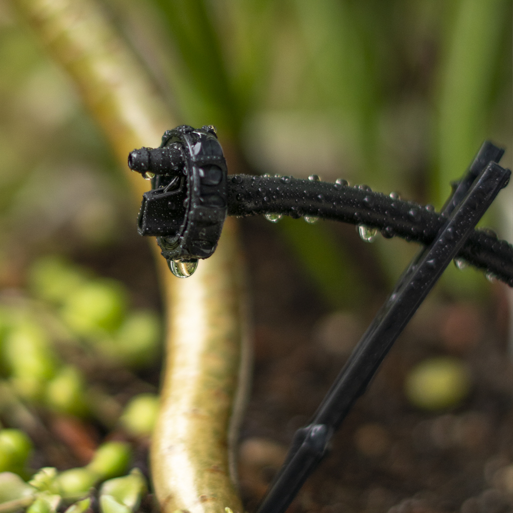
| 1 GPH Black | |
| W221A | 1 GPH Button Drip Emitter (pack of 5) |
| W221B | 1 GPH Button Drip Emitter (pack of 25) |
| W221050 | 1 GPH Button Drip Emitter (pack of 50) |
| 2 GPH Green | |
| W222A | 2 GPH Button Drip Emitter (pack of 5) |
| W222B | 2 GPH Button Drip Emitter (pack of 25) |
| W222050 | 2 GPH Button Drip Emitter (pack of 50) |
Specifications
- Operating pressure: 15-25 PSI
- Recommended operating pressure: 25 PSI (use with model D46 25-PSI pressure regulator)
- Flow rates and color codes:
- Inlet side: ¼ in. barb
- Outlet side: raised nipple
- Materials: polypropylene
- Filter requirement: minimum of 150 mesh
Flow rate in gallon per hour @ 5 to 30 PSI
| Color | Brown | Black | Green |
|---|---|---|---|
| Nominal flow rate | .5 GPH | 1 GPH | 2 GPH |
| 5 PSI | .25 | .5 | 1.0 |
| 10 PSI | .4 | .8 | 1.5 |
| 15 PSI | .5 | 1.0 | 2.0 |
| 20 PSI | .6 | 1.2 | 2.4 |
| 25 PSI | .7 | 1.4 | 2.7 |
| 30 PSI | .8 | 1.5 | 2.9 |
Maximum number of .5 GPH brown button drip emitters on 1/2" drip tubing with .600 ID
| Drip emitters spacing | 1' | 2' | 3' | 4' |
|---|---|---|---|---|
| Flow rate @ 25 PSI | .7 | .7 | .7 | .7 |
| Maximum length | 177 | 282 | 312 | 372 |
| Flow rate in GPM | 2.07 | 1.65 | 1.21 | 1.09 |
| Flow rate in GPH | 123.9 | 98.7 | 72.8 | 65.1 |
| # of drip emitters | 177 | 141 | 104 | 93 |
| Velocity (f/s) | 1.65 | 1.34 | 1.31 | 1.24 |
| Total head loss in PSI | 2.5 | 2.55 | 2.86 | 2.73 |
Maximum number of 1 GPH black button drip emitters on 1/2" drip tubing with .600 ID
| Drip emitters spacing | 1' | 2' | 3' | 4' |
|---|---|---|---|---|
| Flow rate @ 25 PSI | 1.4 | 1.4 | 1.4 | 1.4 |
| Maximum length | 122 | 192 | 246 | 304 |
| Flow rate in GPM | 2.85 | 2.24 | 1.91 | 1.77 |
| Flow rate in GPH | 170.7 | 134.4 | 114.8 | 106.4 |
| # of drip emitters | 122 | 96 | 82 | 76 |
| Velocity (f/s) | 3.24 | 2.54 | 2.18 | 2.01 |
| Total head loss in PSI | 5.2 | 5.24 | 5.01 | 5.29 |
Maximum number of 2 GPH green button drip emitters on 1/2" drip tubing with .600 ID
| Drip emitters spacing | 1' | 2' | 3' | 4' |
|---|---|---|---|---|
| Flow rate @ 25 PSI | 2.7 | 2.7 | 2.7 | 2.7 |
| Maximum length | 80 | 126 | 162 | 200 |
| Flow rate in GPM | 3.60 | 2.84 | 2.43 | 2.25 |
| Flow rate in GPH | 216 | 170.1 | 145.8 | 135 |
| # of drip emitters | 80 | 63 | 54 | 50 |
| Velocity (f/s) | 4.9 | 3.22 | 2.76 | 2.55 |
| Total head loss in PSI | 5.2 | 5.26 | 5.04 | 5.33 |
Videos
-
Demonstration Connecting a Button Dripper to .700 Poly Tubing
-
Demonstration Connecting a PC Drip Emitter to 1/4" Micro Tubing
About
The .5, 1 and 2 GPH W22 Button Drip Emitters are reliable, low cost in-line drip emitters for use in small systems with short run plantings and on flat terrain. One of the main features of these drip emitters is their ability to operate under very low pressures with lower flow rates, making them ideal for gravity feed systems. The three models have preset flow rates of .5, 1 or 2 GPH at a nominal pressure of 15 PSI and can operate under a recommended pressure range of 15 to 25 PSI.
Install the drip emitters either directly into the drip tubing, or at the end of the micro tubing. Within the layout, we highly suggest that a minimum of two drip emitters should be placed on opposite sides of the plant, under the plant canopy, centered between the plant trunk and the plant canopy edge.
When using a single drip emitter, it is important to select the correct flow rate in order to achieve a wetted pattern shape that can cover at least 70% of the plant root zone. In sandy soil, water tends to drain quickly (gravitational force) with little lateral movement, so applying a higher flow rate over a given time period will produce a wider pattern. Using .5 GPH drip emitters for one hour will provide a smaller wetted area then using 1 GPH for the same time, due to the soil characteristics.
One of the most common installation errors in installing drip irrigation is using too few emitters. All too often only a single emitter with preset flow is placed at the base of a newly planted tree, shrub, or rose. In clay soils a single drip emitter can wet a three to four foot diameter; on sandy soils, the same layout using the same drip emitter will only wet an area of few inches. Given the fact that plant roots can grow up to a few feet a year depending on the plant and location, after one year the diameter of the root system would be much larger than the area covered by the one drip emitter. A single drip emitter per tree or shrub could restrict root development as early as the first year after planting unless flow is adjusted or another drip emitter is added. We highly recommend installing more than one drip emitter per plant, depending on plant size.
Installation suggestions
Basic installation recommendations for this product include first reviewing the area and then making a drawing of the garden or site with your preferred layout.
If automation is required, use one of DIG’s hose end timers or battery operated controllers. The ideal controller should have flexible scheduling and two to four start times per day for added flexibility.
Product installation
- Using the drip tubing as the main lateral or as a sub lateral, lay out the drip tubing per your layout drawing. Secure the drip tubing to the ground using stakes (model R60) in key areas and add more stakes as you unroll the drip tubing. Add stakes every 10′-20′ and at the end of each section, or as needed. An extra 1% of drip tubing length should be added to each lateral to compensate for contraction at low temperature.
- Throughout the installation and per your drawing layout, add, if needed, 1/2″ fittings, such as tees (model C35) and elbows (model C36), leaving the end of the drip tubing open. To install the 1/2″ compression drip fittings, cut the drip tubing with a hand pruner, being careful to keep dirt from entering the line. Hold the fitting in one hand and the drip tubing in the other and force the drip tubing into the compression fitting by wiggling it from side to side.
- The drip emitters are installed along the drip tubing at varying or specific intervals. The distribution uniformity of water from the drip emitters along the line depends on the incoming pressure, number of drip emitters used per lateral, and the length of the laterals. Special care should be taken to ensure high uniformity of water along the laterals by not exceeding the product recommendations (see Product Specifications).
- To install the drip emitters, you may use one of the options suggested:Option 1: Direct to 1/2″ tubing: Punch a hole into the side of the drip tubing using the small punch (model D44) or the gun punch (model 16-035), and then snap the barbed side of the drip emitter into the hole.
Option 2: Extended by 1/4″ micro tubing: To reach plants that are not near the 1/2″ line, the drip emitters may be installed at the end of 1/4” micro tubing. To do so, first punch a hole as described in option #1. Then, cut a length of micro tubing (vinyl – models B38 for 50′ and B38100 for 100′, or poly – models B38P for 50′ and B38100B for 100′) to run from the 1/2″ line to the plant, and install a 1/4″ barbed connector (models H80A for pack of 10 and H80B for pack of 50) into one end of the micro tubing. Push the barb into the hole. To the other end of the micro tubing, insert the barbed side of the drip emitter, add a stabilizer stake (model P35B for pack of 10) and secure to the ground. - Open the system valve and flush the line[s]. Lines should be flushed before installing the drip emitters.
- Close the end of the drip tubing using the end cap (model Q58) or figure “8” (model F68B).
- Pressure-test and inspect the system to identify leaks in the drip tubing laterals, fittings and micro tubing and then program the hose end timer or battery operated controller