12-Jet Micro Sprayer
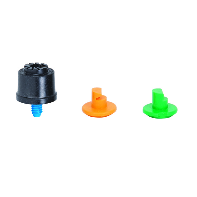
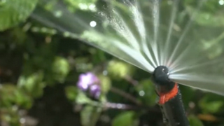
DIG’s model 9950BB 12-Jet Micro Sprayer offers 360° coverage with no moving parts, via a vortex mechanism that utilizes low flow through a large water passage to help prevent clogging. This 10-GPH micro sprayer covers up to 6.5’ full circle, spraying 12 jets streams at 25 PSI. It includes a threaded barb and comes in a pack of three, with two extra spray pattern inserts (180° in orange and 90° in green) included for each. This sprayer can be used for residential gardens, groundcovers, shrubs, hedges and small trees in areas where low-flow overhead irrigation is desired, or for areas where drip emitters or conventional sprinkler systems are not practical. The jet micro sprayer may be placed upright or hung upside down where a very small wetted area is required.
Features
- The 360° pattern can be altered to 180° or 90° with one of two available deflector inserts
- Color-coded deflector inserts for easy identification
- Available in a 360°, 12-jet pattern and includes three of each additional spray pattern inserts with 180° in orange and 90° in green
- Efficient and reliable method to apply water
- Can be attached into the end of 1/4″ micro tubing or into the 1/2″ drip tubing.
- Trouble-free operation with no moving parts
- Low flow with large droplet size in a 360°, 12-jet pattern
- Constructed of UV-resistant, durable plastic material
How to Order
| MODEL | DESCRIPTION |
|---|---|
| 9950BB | Twelve Jet Micro Sprayer with 10/32 in. Threaded Barb (pack of 3) |
Specifications
- Operating pressure range: 15 to 30 PSI
- Flow rate: 10.0 @ 25 PSI
- Pattern: 360°, 12-jet spray pattern and spray pattern inserts for 180° in orange and 90° in green
- Wetting area range: 4.0' to 8.5’
- Filter requirement: minimum of 120 mesh
- Recommended spacing: 2' to 4' apart
- Material: high-impact plastic
Flow rate, radius and diameter
| Pressure | Spray | Flow rate | c2 Radius | cx | Diameter |
|---|---|---|---|---|---|
| PSI | base | GPH | 90° | 180° | 360° with 12 jets |
| 15 | blue .051" | 7.5 | 4.0' | 4.9' | 4.3' |
| 20 | blue .051" | 8.8 | 5.0' | 6.9' | 5.7' |
| 25 | blue .051" | 10.0 | 5.5' | 8.0' | 6.5' |
| 30 | blue .051" | 11.0 | 6.0' | 8.5' | 6.9' |
Videos
-
Demonstration Connecting a Micro Sprayer to .700 Poly Tubing
About
The 9950BB 12-Jet Micro Sprayer on 12/24 large thread sprays water in a full-circle, flat pattern and has a flow range from 7.5 to 11.0 GPH at 15 to 30 PSI. It comes in a one-piece construction that includes thread to connect into micro tubing, directly into drip tubing or that can be extended using a PE riser. The jet micro sprayer also includes inserts that can snap on top of the jet and replace the 360°, 12-jet pattern with a 90° or 180° flat spray pattern. It should be used where overhead watering is suggested, on any type of planting, including small and large trees, shrubs, flowerbeds and groundcovers.
For complete coverage of an area, the recommended spacing is 2’ to 4’ between each micro spray head to a maximum distance of 52′ to 84’ in length, using 1/2” drip tubing as the main lateral. Like micro sprinklers, these micro mist sprayers operate at low pressure and require a filter to protect the water passages of the sprayer. The main advantage of using the 12-jet micro sprayer for irrigation is that a relatively large number of micro sprayers can operate simultaneously with a small sized pipe.
Installation suggestions
Basic installation recommendations for this product include first reviewing the area and then making a drawing of the garden or site with your preferred layout.
If automation is required, use one of DIG’s hose end timers or battery operated controllers. The ideal controller should have flexible scheduling and two to four start times per day for added flexibility.
Start the installation from a PVC pipe or to pipe thread
- If the system installation is started from a PVC pipe, first shut off the main water supply.
- If an automated system is preferred, we recommend installing a 3/4” ball valve or gate valve before the battery operated controller or AC valve, if used. This ball valve can be very useful as an emergency backup to turn the system off. This type of arrangement is used by professional installers.
- Turn the water supply on to flush the line and then shut the water supply off using the new ball or gate valve.
- Install an AC valve or battery operated controller, wrapping TEFLON tape on all the male thread fittings used.
- Turn the water supply on again to pressurize the system. The unit will open momentarily and then will shut off.
- Test the valve or the battery operated controller and make sure that it is working correctly.
- After the AC valve or battery operated controller, add a 3/4” screen filter with 155-mesh (model D55). The screen filter is used to protect the drip system. Then, add a preset 25 PSI pressure regulator (model D46P) or adjustable pressure regulator (model PRV075) for operating under higher pressure. The pressure regulator is used to lower the pressure to the suggested operating pressure for micro sprinklers and micro sprayers. Follow with a 3/4” swivel adapter (model 50001) to the drip tubing or 3/4” PVC thread x slip adapter to the PVC line.
Start the installation from a faucet or hose thread
- If an automated system is preferred, install a hose end timer.
- Test the timer and make sure that it is working correctly, then program it (SEE STEP 8 BELOW). To the timer, add a backflow device (model D45), then a 25 PSI pressure regulator (model D46) and follow with a 3/4″ swivel adapter with a screen (model C34). If water quality is a concern, we highly recommend using a fine mesh 3/4″ filter with 155 mesh (model D57A).
Product installation
- Using the drip tubing as the main lateral or as a sub lateral, lay out the drip tubing per your layout drawing. Secure the drip tubing to the ground using stakes (model R60) in key areas and add more stakes as you unroll the drip tubing. Add stakes every 20′-30’ and at the end of each section, or as needed. An extra 1% of drip tubing length should be added to each lateral to compensate for contraction at low temperature.
- Throughout the installation and per your drawing layout, add, if needed, 1/2” fittings, such as tees (model C35) and elbows (model C36), leaving the end of the drip tubing open. To install the 1/2″ compression drip fittings, cut the drip tubing with a hand pruner, being careful to keep dirt from entering the line. Hold the fitting in one hand and the drip tubing in the other and force the drip tubing into the compression fitting by wiggling it from side to side.
- The micro sprayers are installed along the drip tubing at varying or at specific intervals or one per tree. The distribution uniformity of water from the micro sprayers along the line depends on the incoming pressure, number of micro sprayers used per lateral and the length of the laterals. Special care should be taken to ensure high uniformity of water along the laterals by not exceeding the product recommendations (see chart).
- To install the micro sprayer, cut a piece of 1/4” micro tubing (not to exceed four feet) (vinyl – models B38 for 50’ and B38100 for 100’ or poly – B38P for 50’ and B38100B for 100’). To the micro tubing end, insert a 1/4” barb (models H80A for pack of 10 and H80B for pack of 50). To the other end of the micro tubing, thread the micro sprayer. Use a long stake (model R66) to secure the micro sprayer to the ground, keeping the micro sprayer head at a minimum of 8” to 10” above ground for best coverage. Punch a hole into the drip tubing using the small punch (model D44) or the gun punch (model 16-035), and snap the 1/4” barb at the end of the micro tubing into the drip tubing.
- To change the pattern from 360° to 180° or 90°, snap one of the color-coded inserts to the top of the 12-jet micro sprayer.
- Turn the water on and flush the line.
- Close the end of the drip tubing using the hose end (model Q58) or figure “8” (model F68B).
- Pressure-test the system to identify leaks in the drip tubing laterals, fittings and micro tubing, and then program the hose end timer or battery operated controller.