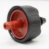
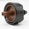
PC Button Drip Emitters
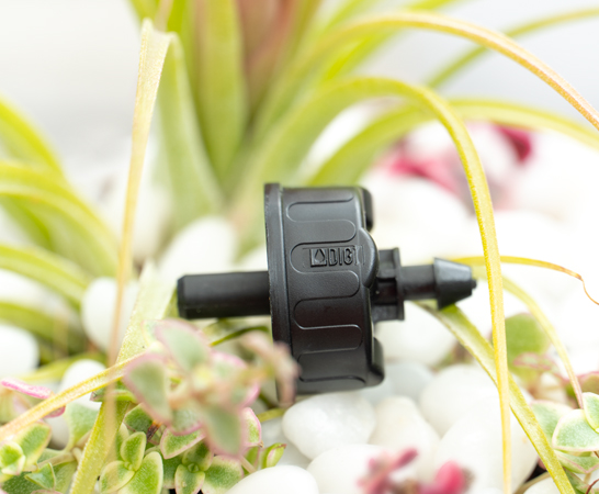
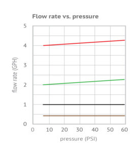
DIG Pressure Compensating (PC) Button Drip Emitters are designed to produce a consistent flow rate over a pressure range of 7.25 to 58 PSI. DIG PC drip button emitters are continuously adjusting to varying water pressures, ensuring a constant flow from each drip emitter regardless of pressure fluctuations or varying elevations along the line. The PC drip emitters are available in .5, 1, 2 and 4 GPH and includes models, B2205B/B2205-25PC (.5-GPH, pack of 10 or 25), B221B/B221-25PC (1-GPH, pack of 10 or 25), B222B/B222-25PC (2-GPH, pack of 10 or 25) and B224B/B224-25PC (4-GPH, pack of 10 or 25). Used for flowers, shrubs groundcovers and trees, DIG PC drip emitters offer a convenient way to water both, new and existing landscapes, including difficult terrain such as slopes, oddly shaped areas and sites with high winds.
Features
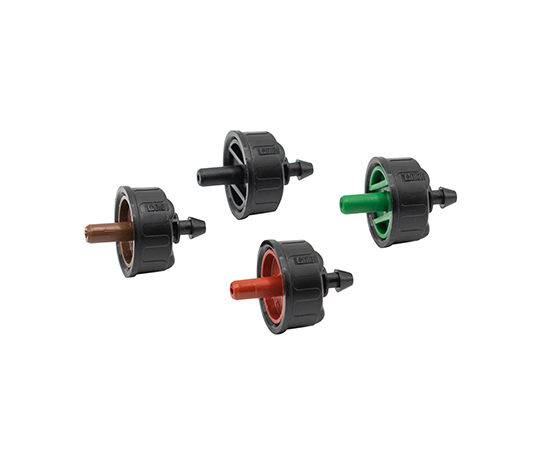
- Available in four colors so that it is easy to identify flow rate
- Ideal use is for slopes, oddly shaped areas, sites with high winds and long runs.
- Pressure compensating feature enables the use of longer laterals under a wide range of pressures
- Turbulent flow through a large labyrinth water passage and floating diaphragm help prevent clogging
- Contain a diaphragm that continuously adjusts to varying water pressure to ensure a constant flow rate, even in challenging topographical conditions
- Raised nipple outlet prevents water runoff along the drip lateral
- Resistant to chemicals and fertilizers used in landscape application
- Quarter inch barbed inlet for installation into drip tubing or 1/4″ distribution tubing
- Use for any layout in residential gardens
- Constructed of UV-resistant, durable plastic material to withstand the most adverse conditions
- Available in four color-coded flow rates for easy identification
- Pressure compensation enables the use of longer laterals with smaller diameter tubing
How to Order
| MODEL | DESCRIPTION | COLOR | IMAGE |
|---|---|---|---|
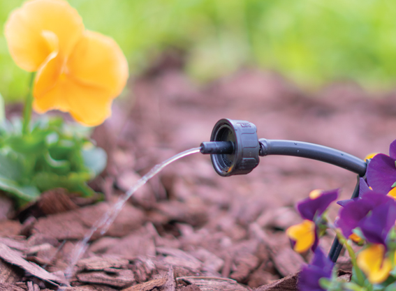
| B221B & B221B-25PC | 1 GPH Pressure Compensating (PC) Drip Emitters (pack of 10 and pack of 25) | Black |
|
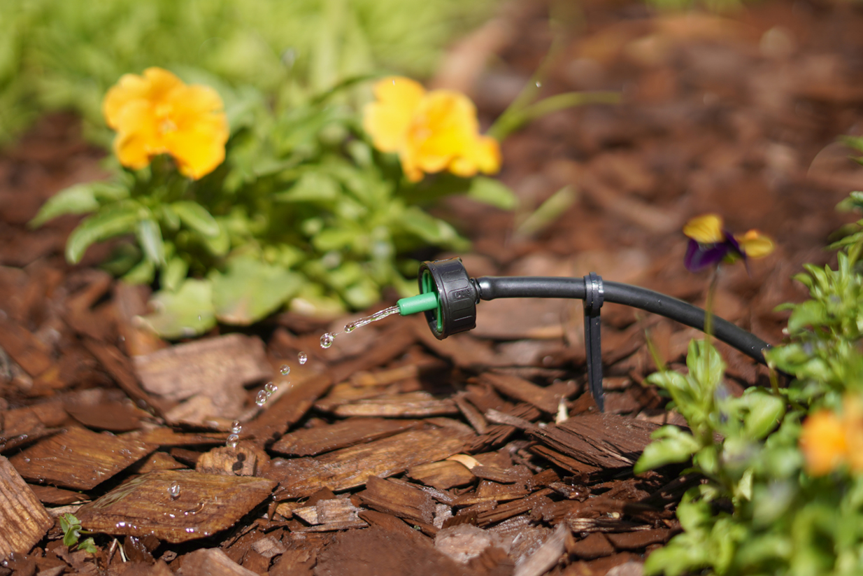
| B222B & B222B-25PC | 2 GPH Pressure Compensating (PC) Drip Emitters (pack of 10 and pack of 25) | Green |
|
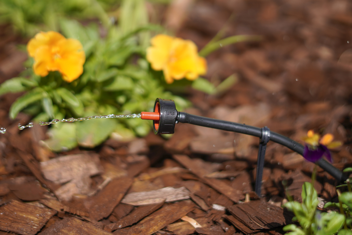
| B224B & B224B-25PC | 4 GPH Pressure Compensating (PC) Drip Emitters (pack of 10 and pack of 25) | Red |
|
| B2205B & B2205B-25PC | .5 GPH Pressure Compensating (PC) Drip Emitters (pack of 10 and pack of 25) | Brown |
|
Specifications
-
- Operating pressure:
- 7.25 - 58 PSI (.5 - 4 BAR)
- Flow rates and color codes:
- .5 GPH (1.78 L/H) color code – brown
- 1 GPH (4 L/H) color code – black
- 2 GPH (7.60 L/H) color code – green
- 4 GPH (15.5 L/H) color code – red
- Inlet size:
- 1/4" (4 mm) barb
- Outlet size:
- 1/4" nipple
- Filter requirement:
- 120 mesh/130 microns for .58 GPH (2.2 L/H) or lower
- 150 mesh/100 microns for 1 GPH (3.8 L/H) or higher
- Filter selection depends on water quality and concentration of dirt particles
- Materials:
- Body and cover: polypropylene
- Diaphragm: silicone
- Operating pressure:
About
The .5, 1, 2 and 4 GPH PC Drip Emitters contain a silicon diaphragm that continuously adjusts to varying water pressures and at the same time allows particles to pass through the drip emitter’s water passage, providing reliable performance and a longer life. This method of flushing with a large flow path allows the drip emitters to operate at optimal flow rates under extreme conditions. These three models of PC Drip Emitters discharge the same amount of water under a pressure range of 7.25 to 58 PSI, allowing for higher uniformity and longer lateral run on any topography. This feature allows the number of drip emitters on a single drip tubing to be maximized while maintaining an even flow rate from each emitter along the line.
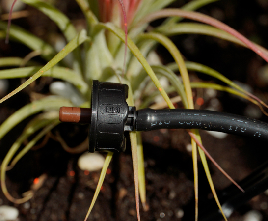
Install the drip emitters using one of two methods; either directly into the drip tubing, or at the end of the micro tubing. Within the layout, we highly suggest that a minimum of two drip emitters should be placed on opposite sides, under the plant canopy, centered between the plant trunk and the plant canopy edge.
When using single drip emitters, it is important to select the correct flow rate in order to achieve a wetted pattern shape that can cover at least 70% of the plant root zone. In sandy soil, water tends to drain quickly (gravitational force) with little lateral movement, so applying a higher flow rate over a given time period will produce a wider pattern. Using .5 GPH drip emitters for one hour will provide a smaller wetted area then using 1 GPH for the same time, due to the soil characteristics.
One of the most common installation errors in installing drip irrigation is using too few emitters. All too often only a single emitter with preset flow is placed at the base of a newly planted tree, shrub or rose. In clay soils, a single drip emitter can wet a three to four foot diameter; on sandy soils, the same layout using the same drip emitter will only wet an area of a few inches. Given the fact that plant roots can grow up to a few feet a year depending on the plant and location, after one year the diameter of the root system would be much larger than the area covered by the one drip emitter. A single drip emitter per tree or shrub could restrict root development as early as the first year after planting if flow is not adjusted or a drip emitter is not added. We highly recommend adding more than one drip emitter per plant, depending on plant size.
Installation suggestions
Basic installation recommendations for this product include first reviewing the area and then making a drawing of the garden or site with your preferred layout. If automation is required, use one of DIG’s hose end timers or battery operated controllers. The ideal controller should have flexible scheduling and two to four start times per day for added flexibility.
Start the installation from a PVC pipe or to pipe thread
Recommendations: Wrap all male pipe thread fittings with Teflon tape. Do not use pipe cement on the valve as it will damage the valve and void the warranty.
- If the system installation is started from a PVC pipe, first shut off the main water supply.
- If an automated system is preferred, we recommend installing a 3/4″ ball or gate valve before the battery operated controller or AC valve, if used. This ball valve can be very useful as an emergency backup to turn the system off. This type of arrangement is used by professional installers.
- Turn the water supply on to flush the line and then shut the water supply off using the new ball or gate valve.
- Install an AC valve or battery operated controller, wrapping TEFLON tape on the male pipe thread fittings.
- Turn the water supply on again to pressurize the system. The unit will open momentarily and then will shut off.
- Test the valve or the battery operated controller and make sure that it is working correctly.
- After the AC valve or battery operated controller, add a 3/4″ screen filter with 155-mesh (model D55). The screen filter is used to protect the drip system. Then, add a preset 25 PSI pressure regulator (model D46P) or adjustable pressure regulator (model PRV075). The pressure regulator is used to lower the pressure to the suggested operating pressure for a drip system. Follow with a 3/4″ swivel adapter (model 50001) to the drip tubing or 3/4″ PVC thread x slip adapter to the PVC line.
Start the installation from a faucet or hose thread
- If an automated system is preferred, install a hose end timer.
- Test the hose end timer and make sure that it is working correctly.
- After the timer, add a backflow device (model D45) and then add a 3/4″ filter (model D57A) to protect the drip system. Next, install a 25 PSI pressure regulator (model D46) to lower the pressure to the drip system, followed by a swivel adapter (model C34) to connect the drip tubing.
Product installation
- Using the drip tubing as the main lateral or as a sub lateral, lay out the drip tubing per your layout drawing. Secure the drip tubing to the ground using stakes (model R60) in key areas and add more stakes as you unroll the drip tubing. Add stakes every 20′-30′ and at the end of each section, or as needed. An extra 1% of drip tubing length should be added to each lateral to compensate for contraction at low temperature.
- Throughout the installation and per your drawing layout, add, if needed, 1/2″ fittings, such as tees (model C35) and elbows (model C36), leaving the end of the drip tubing open. To install the 1/2″ compression drip fittings, cut the drip tubing with a hand pruner, being careful to keep dirt from entering the line. Hold the fitting in one hand and the drip tubing in the other and force the drip tubing into the compression fitting by wiggling it from side to side.
- The drip emitters are installed along the drip tubing at varying or specific intervals. The distribution uniformity of water from the drip emitters along the line depends on the incoming pressure, number of drip emitters used per lateral and the length of the laterals. Special care should be taken to ensure high uniformity of water along the laterals by not exceeding the product recommendations (see Product Specifications).
- To install the drip emitter, you may use one of the options suggested:
- Option 1: Punch a hole into the drip tubing using the small punch (model D44) or the gun punch (model 16-035), and snap the barbed side of the drip emitter into the drip tubing
- Option 2: Install the drip emitters into the micro tubing by cutting a length of two to four feet (we highly recommend not exceeding four feet) of 1/4″ micro tubing (vinyl – models B38 for 50′ and B38100 for 100′, or poly – models B38P for 50′ and B38100B for 100′). To the micro tubing end, insert a 1/4″ barb (model H80A for pack of 10 and model H80B for pack of 50). To the other end of the micro tubing, insert the barbed side of the drip emitter, add a stabilizer stake (model P35B for pack of 10) and secure to the ground. Punch a hole into the drip tubing using the small punch (model D44) or the gun punch (model 16-035), and insert the 1/4″ barb at the end of the micro tubing into the drip tubing.
- Turn the water on and flush the line.
- Close the end of the drip tubing using the hose end (model Q58) or figure “8” (model F68B).
- Pressure-test the system to identify leaks in the drip tubing laterals, fittings and micro tubing, and then program the hose end timer or battery operated controller.