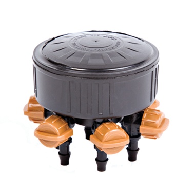
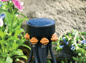
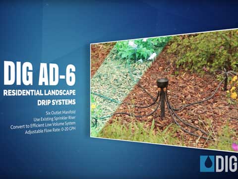
6-Outlet Adjustable Drip Manifold

DIG’s Adjustable Six-Outlet PC Drip Manifold (1/2″ female pipe thread) is used to retrofit an existing 1/2” sprinkler riser into a six-outlet drip irrigation system without altering or increasing the total flow of the sprinkler system zone. It has six independently adjustable, pressure compensating outlets with flow rates between 0 and 20 GPH at operating pressures of up to 50 PSI. The manifold’s six rotating 1/4” barbed outlets have flow control knobs which offer installation flexibility when the unit is incorporated into a new system or when replacing any of the sprinkler heads in a zone. Each outlet accepts 1/4″ micro tubing, 1/4” soaker hose or the addition of drip emitters and adjustable stakes to bring water to each plant root zone at a maximum flow of 20 GPH per outlet.
Features
- Replacing the sprinkler riser with the six-outlet manifold can lead to water savings of 50% to 70%.
- Each outlet has a swivel barb with flow control knob that allows flow adjustment and installation flexibility
- Allows incorporation of 1/4” drip line, 1/4” soaker hose or the use of drip emitters to a maximum flow of 20 GPH per outlet
- Replacing a sprinkler head with drip irrigation can eliminate wet walls and discoloration and staining of fences and windows
- Designed for new and existing landscapes, including oddly shaped areas where a sprinkler head cannot provide good coverage
- No special tools or glue are needed
- DIG’s drip irrigation products may be exempt from residential and commercial watering restrictions (check local codes)
- Install above grade, or place below grade in a six-inch emitter box
- Use with any brand’s 1/4″ micro tubing

How to Order
| MODEL | DESCRIPTION |
|---|---|
| AD6 | 6-outlet Adjustable Drip Manifold with 1/2 in. FNPT |
Specifications
- Operating pressure: 15-50 PSI
- Flow rate is adjustable between 0-20 GPH per each outlet
- Total flow rate: 120 GPH with valves completely open
- Inlet size: 1/2" female pipe thread (FNPT)
- Temperature range: up to 122°F (50°C)
- Outlet size: 1/4" barbed mini valve per each outlet
- Accepts 1/4” micro tubing with .150 to .170 ID and 1/4" drip line
- Filter requirement: min. of 40 mesh
- Materials:
- Body and cover: high-impact plastic
- Barbed valve: high-impact plastic
- Diaphragm: EPDM
About
The AD6 Adjustable Six-Outlet PC Drip Manifold is utilized on new or existing installations to retrofit a sprinkler riser into a drip irrigation system, applying 50% to 70% less water than a conventional sprinkler system by applying the water directly to the plant roots. It has six outlets with individual adjustable flow controls with a range of 0 to 20 GPH. The manifold offers greater installation flexibility by allowing incorporation of 1/4” drip line, 1/4” soaker hose or the use of drip emitters to a maximum flow of 20 GPH per outlet. It can be used to cover individual plants or closely spaced groups of plants within the layout.
Installation suggestions
Retrofitting a conventional sprinkler riser to a water-saving drip irrigation system requires a few simple steps including evaluation of the areas to be watered, selection of the best method to water and selection of the flow rate. The most suitable uses for a drip system include watering shrubs, trees, roses, pots, individual plants or groups of plants that can be irrigated more efficiently using a drip irrigation system.
- First, we recommend using the six-outlet manifold in an area where the plants are close to the sprinkler riser you are replacing, using short lengths of micro tubing, not exceeding six to eight feet from the riser and not exceeding a total flow of 20 GPH with all other
devices added. - Remove the sprinkler from the riser.
- Turn the water on to flush the line. Then shut off the water and thread the six-outlet manifold onto the riser.
- From the manifold outlets, extend 1/4” micro tubing to the plant areas (models B38 for 50’ and B38100 for 100’). At this point you have a number of options:
a. Secure the end of the micro tubing with a stake (model P35B, pack of 10). This option will allow for a flow of 0 to 20 GPH from each outlet used.
b. To the end of the micro tubing, insert a 1/4” barb (model H80A, pack of 5), connect 1/4″ dripline (.5 GPH drip emitter every 9″ or 12″) or soaker hose (model PSH50 porous soaker hose) and loop it around the plant. This option will provide a larger wetted area
under the plant canopy and provide even water distribution from each of the six outlets.
c. To the end of the micro tubing, insert a 1/4” tee (model H82A, pack of 5). From the tee, extend additional lengths of micro tubing and insert a 4-GPH PC drip emitter or adjustable drip emitter (models B224B, pack of 10 or B10B, pack of 10) with the drip emitters placed under the
plant canopy, at the center between the plant trunk and the plant canopy edge. - Connect the micro tubing onto the barbed outlet.
- Turn the water on and check the system, making sure that all outlets are working and the location of each outlet meets your needs, adjusting the flow on each outlet as needed.

