Spray Jets
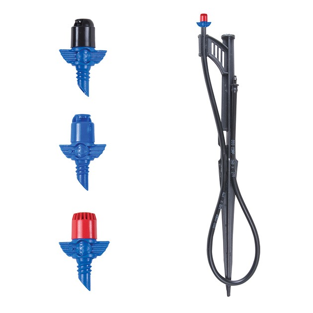
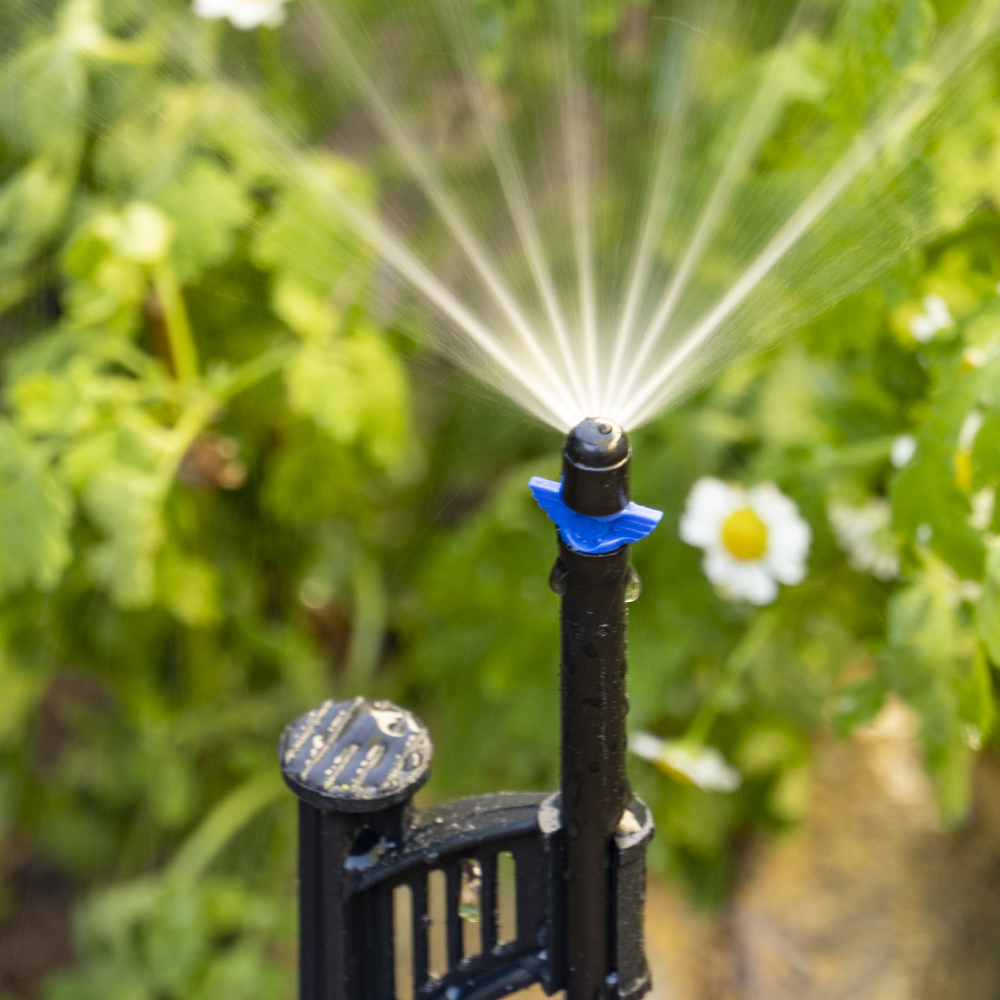
DIG’s Micro Sprayers are low flow with full, half, quarter circle or strip spray patterns and a flow rate of 13.4 gallons per hour at 25 PSI. The 110B, 111B and 112B have a threaded barb and are available in packs of 10; the 110-1B, 111-1B and 112-1B, assembled with a 13” stake and 24” micro tubing with a 1/4″ barb for installation flexibility, are available in packs of one. Producing a fine spray in a range of patterns, the micro sprayers can cover areas from a 5.9’ radius to 19.8’ in full diameter, depending on the spray pattern. The low-precipitation-rate micro sprayers can be used for most planting areas and are suggested when low-flow overhead irrigation is desired or for an area where drip emitters or conventional sprinkler systems are not practical. They are assembled with two nonmoving parts and have no flow adjustment capability.
Features
- Available in 90°, 180°, 360° and strip spray patterns, and used for closely spaced plantings
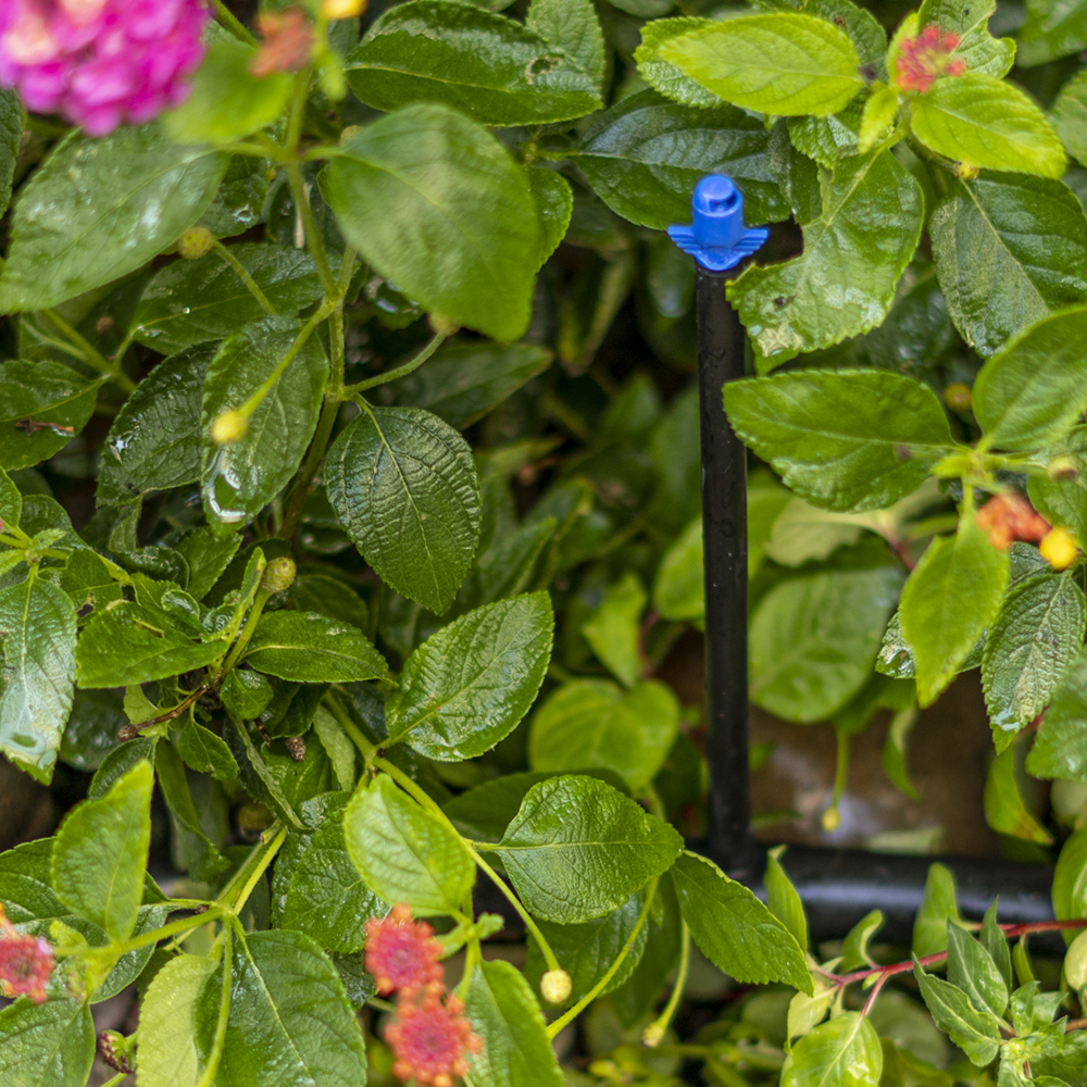
- Recommended for flowerbeds, groundcovers, shrubs or for areas where low-flow overhead irrigation is desired
- Available completely assembled on a 13″ spike with 24” (.160 ID x .270 OD) micro tubing and a 1/4″ barb or threaded barb
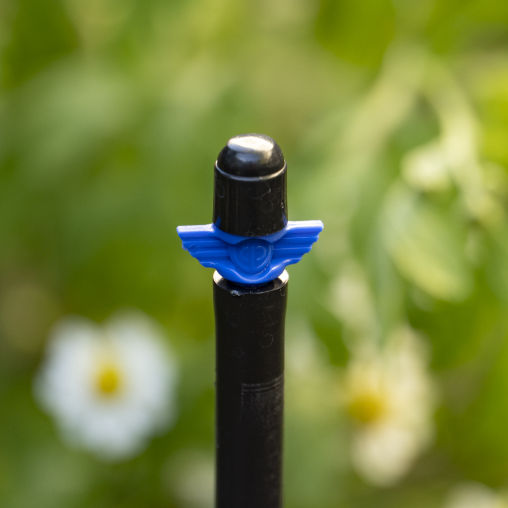
- Two-piece micro sprayer consisting of a spray cap and threaded base for installation flexibility
- Efficient and reliable method to apply water
- Low flow with fine spray pattern
- Color-coded spray caps signify various spray patterns for easy identification
- Removable cap for easy cleaning
- Constructed of UV-resistant, durable plastic material
How to Order
| MODEL | DESCRIPTION | COLOR |
|---|---|---|
| 90° pattern – coverage up to 8.5 ft. radius | ||
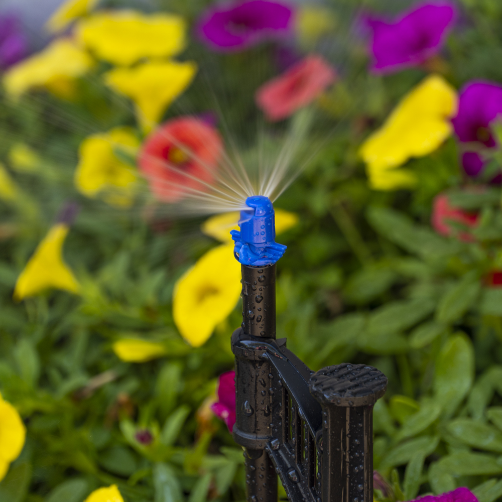
| 110B | 90° Spray Jet on Threaded Barb (pack of 10) | Blue/black |
| 110-1B | 90° Spray Jet Complete Assembly (pack of 1) | Blue/black |
| 180° pattern – coverage up to 6.9 ft. radius | ||
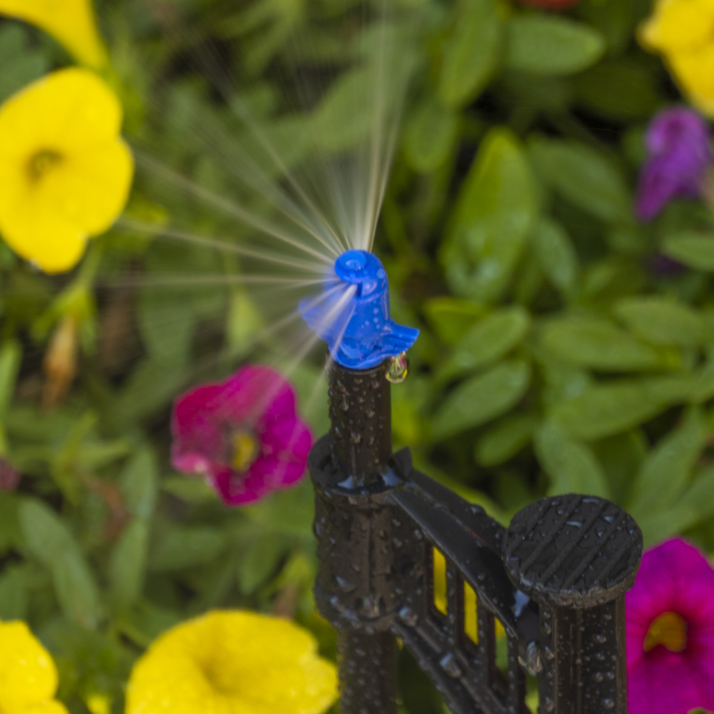
| 111B | 180° Spray Jet on Threaded Barb (pack of 10) | Blue/blue |
| 111-1B | 180° Spray Jet Complete Assembly (pack of 1) | Blue/blue |
| 360° pattern – coverage up to 18.4 ft. diameter | ||
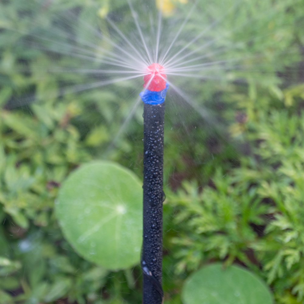
| 112B | 360° Spray Jet on Threaded Barb (pack of 10) | Blue/red |
| 112-1B | 360° Spray Jet Complete Assembly (pack of 1) | Blue/red |
Specifications
- Operating pressure range: 15 to 30 PSI
- Recommended operating pressure: 25 PSI (use with model D46 25-PSI pressure regulator)
- Flow rate: 13.4 GPH @ 25 PSI
- Filter requirement: minimum of 120 mesh
- Recommended micro sprayer spacing: 4' to 8' apart
- Micro tubing length & size: 24" x 1/4" with .160 ID x .270 OD
- Material
- Stake: polypropylene
- Micro sprinkler: high-impact plastic
Flow rate, radius and diameter
| Pressure | Spray | Flow rate | c2 Radius | cx | Diameter |
|---|---|---|---|---|---|
| PSI | base | GPH | 90° | 180° | 360°-18 jets |
| 15 | Blue.04" | 10.5 | 6.6' | 5.9' | 15.2' |
| 20 | Blue.04" | 12 | 7.6' | 6.4' | 16.9' |
| 25 | Blue.04" | 13.4 | 8.5' | 6.9' | 18.4' |
| 30 | Blue.04" | 14.7 | 9.3' | 7.3' | 19.8' |
Maximum number of micro sprayers on 1/2" drip tubing with .600 ID
| Micro sprayer spacing | 4' | 5' | 6' | 7' | 8' |
|---|---|---|---|---|---|
| Flow rate @ 25 PSI | 13.4 | 13.4 | 13.4 | 13.4 | 13.4 |
| Maximum Length | 68 | 80 | 90 | 105 | 112 |
| Flow rate in GPM | 3.80 | 3.57 | 3.35 | 3.35 | 3.13 |
| Flow rate in GPH | 227.8 | 214.4 | 201 | 201 | 187.6 |
| # of micro sprayers | 17 | 16 | 15 | 15 | 14 |
| Head Loss in PSI | 4.7 | 4.9 | 4.9 | 5.7 | 5.4 |
| Velocity (f/s) | 4.31 | 4.05 | 3.8 | 3.8 | 3.55 |
| 24" micro tubing head loss | 0.3 | 0.3 | 0.3 | 0.3 | 0.3 |
| Total head loss at the spray head | 5.0 | 5.2 | 5.2 | 6.0 | 5.7 |
Videos
-
Demonstration Connecting a Micro Sprayer to .700 Poly Tubing
Abouts
The Micro Sprayers are available with a preset flow rate of 13.4 GPH at 25 PSI and coverage of up to an 8.5’ radius and 18.4’ full circle, depending on the assembly used and the height of the micro sprayers above ground. Using a PE riser extension, the height of the sprayers can be adjusted to fit taller plants and higher vegetation growth. Use the micro sprayers when overhead watering is suggested on any type of planting, including vegetation that requires moisture, groundcovers, flowerbeds or individual trees along the poly tubing. The recommended spacing is 4’ to 8’ between the spray heads or one per tree to a maximum distance of 68’ to 112’ in length using the 1/2” drip tubing as the main lateral.
The micro sprayers are an efficient and reliable method to apply water. To cover densely planted areas, place the micro sprayers close together in rectangular or triangular spacing for good overlapping irrigation and better uniformity. Do not use the micro sprayers in windy areas as the micro sprayers’ small-sized droplets can be easily dispersed in the air, even under low to moderate wind conditions, adversely affecting uniformity. The main advantage of low-flow micro irrigation is that a relatively large number of micro sprayers can operate simultaneously.
Installation suggestions
Basic installation recommendations for this product include first reviewing the area and then making a drawing of the garden or site with your preferred layout.
If automation is required, use one of DIG’s hose end timers or battery operated controllers. The ideal controller should have flexible scheduling and two to four start times per day for added flexibility.
Start the installation from a PVC pipe or to pipe thread
- If the system installation is started from a PVC pipe, first shut off the main water supply.
- If an automated system is preferred, we recommend installing a 3/4” ball valve or gate valve before the battery operated controller or AC valve, if used. This ball valve can be very useful as an emergency backup to turn the system off. This type of arrangement is used by professional installers.
- Turn the water supply on to flush the line and then shut the water supply off using the new ball or gate valve.
- Install an AC valve or battery operated controller, wrapping TEFLON tape on all the male thread fittings used.
- Turn the water supply on again to pressurize the system. The unit will open momentarily and then will shut off.
- Test the valve or the battery operated controller and make sure that it is working correctly. If using a battery operated controller, program it.
- After the AC valve or battery operated controller, add a 3/4” screen filter with 155-mesh (model D55). The screen filter is used to protect the drip system. Next, add a preset 25 PSI pressure regulator (model D46P) or adjustable pressure regulator (model PRV075). The pressure regulator is used to lower the pressure to the suggested operating pressure for a drip system. Follow with a 3/4” swivel adapter (model 50001) to the drip tubing or 3/4” PVC thread x slip adapter to the PVC line.
Start the installation from a faucet or hose thread
- If an automated system is preferred, install a hose end timer.
- Test the hose end timer and make sure that it is working correctly, then program it. To the hose end timer, add a backflow device (model D45), then a 25 PSI pressure regulator (model D46) and follow with a 3/4″ swivel adapter with a screen (model C34). If water quality is a concern, we highly recommend using a fine mesh 3/4″ filter with 155-mesh (model D57A).
Product installation
- Using the drip irrigation tubing as the main lateral or sub lateral, lay out the drip tubing per your layout drawing. Secure the drip tubing to the ground using stakes (model R60). Use the stake holders to secure the drip tubing to the ground in key areas and add more stakes as you unroll the drip tubing. Add stakes every 20′-30’ and at the end of each section, or as needed. An extra 1% of drip irrigation tubing length should be added to each lateral to compensate for contraction at low temperature.
- Throughout the installation and per your drawing layout, add, if needed, 1/2” fittings, such as tees (model C35) and elbows (model C36), leaving the end of the drip tubing open. To install the 1/2″ compression drip fittings, cut the drip tubing with a hand pruner, being careful to keep dirt from entering the line. Hold the fitting in one hand and the drip tubing in the other and force the drip tubing into the compression fitting by wiggling it from side to side.
- The micro sprayers are installed along the drip tubing at varying or at specific intervals. The distribution uniformity of water from the micro sprayers along the line depends on the incoming pressure, number of micro sprayers used per lateral and the length of the laterals. Special care should be taken to ensure high uniformity of water along the laterals by not exceeding the product recommendations (see chart).
- To install the micro sprayers use one of following suggested options:Option one: Cut a length of two to four feet of 1/4” micro tubing (not to exceed four feet) (vinyl – models B38 for 50’ and B38100 for 100’, and poly – B38P for 50’ and B38100B for 100’). To the micro tubing end, insert a 1/4” barb (models H80A for pack of 10 and H80B for pack of 50). To the other end of the micro tubing, thread the micro sprayer and clip it to a clip stake (model R66). Insert the clip stake to the ground, keeping the micro sprayer head at a minimum of six to eight inches above ground for best coverage. Punch a hole into the drip tubing using the small punch (model D44) or the gun punch (model 16-035), and snap the 1/4” barb at the end of the micro tubing into the drip tubing.
Option two: To install the 10/32 thread micro sprayer, punch a hole into the upper side of the drip tubing using the small punch (model D44) or the gun punch (model 16-035), snap the 1/4” barb at the end of the PE riser assembly (model P34B) into the drip tubing and thread the spray head into the PE riser.
Option three: To install the complete-assembly micro sprayer, punch a hole into the side of the drip tubing using the small punch (model D44) or the gun punch (model 16-035), snap the 1/4” barb at the end of the 24” micro tubing assembly into the drip tubing and insert the stake to the ground, keeping the micro sprayer head at a minimum of eight inches above ground for best coverage. - Turn the water on and flush the line.
- Close the end of the drip tubing using the hose end (model Q58) or figure “8” (model F68B).
- Pressure-test the system to identify leaks in the drip tubing laterals, fittings and micro tubing, and then program the hose end timer or battery operated controller.